WORKING AREA: DETAILED LIST
On this screen you can see the information about the different parts or components that make the closet (name, dimensions, finishes, grain, etc.).
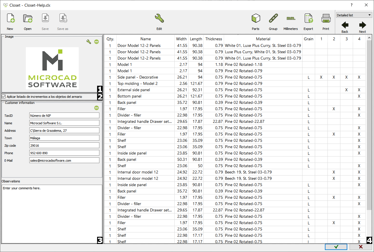
1)IMAGE
You can add an image or logo to our budget by clicking on the ( ) button. A Windows explorer will open where you can select the .BMP file. Press the (
 ) button to delete the previously selected image.
2)APPLY LIST OF INCREMENTS TO CLOSET OBJECTS
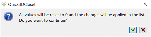
By checking this option, the increments configured here will be applied to the different parts of the closet.
3)CUSTOMER INFORMATION AND OBSERVATIONS
Add the customer info (TaxID, Name, Address, Town, Zip code, E-mail), as well as some "Observations". Click on the ( ) button to delete all the information.
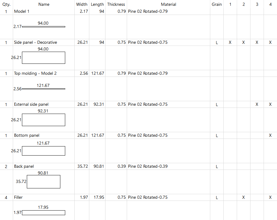
4)CABINET PARTS LIST
On the right side you can find a list with all the parts and elements that make up our closet, as well as their measurements, materials, quantity, edging, etc.
ICONS MENU
The following options will be activated in the "Detailed list" view:


|
|
PARTS: Shows every part or component including a basic drawing of it with dimensions. (NOTE: Images are not available when exporting the file to Excel).
|

|
|
GROUP: Combines same parts and provides a total. This report can be exported to Excel. |

|
|
MILIMETERS: Shows all part dimensions in millimeters. When pressing the button twice, it reverts the part dimensions to inches. |

|
|
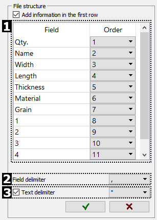
EXPORT: The parts list information can be saved in several different formats. When pressing Export, the following window appears:
The available file formats include Ardis, Biesse, Cutlist Plus 2006, Eurosoft, Magi-Cut, Ms Excel, Opticut, Optimik, Optimik 3.xx, User and Woodge. Select one from the pull down menu and press the wrench icon (
Click on the "Green check mark" to generate the user report. |


|
|
PRINT: Click here to print the "Parts list".
|

